Getting Started with the Quartet Carrier Board
This application note described how to get started with a Quartet Carrier Board and Blackfly S USB3 Board-level camera.
Supported Products
Teledyne FLIR offers a Quartet carrier board with or without a TX2 module for easy integration of up to four USB3 board-level cameras.
- ACC-01-6005—Quartet Carrier with TX2 module 8 GB
- ACC-01-6004—Quartet Carrier with TX2 module 4 GB
- ACC-01-6003—Quartet Carrier without TX2 module
Do you have the parts you need?
To get started with Quartet, you need the following components:
- Quartet carrier board
- Power adapter
- Micro SD card
- FPC cable—ACC-01-2404 (30 mm), ACC-01-2405 (15 cm), ACC-01-2401 (30 cm)
- Blackfly S USB3 Board-level camera (multiple models available)
If you purchased from Teledyne, the Micro SD card is preloaded with an image to allow for the Quartet to boot up and have the Spinnaker SDK installed. If you purchased from a third-party, you need to flash the Micro SD card with a boot up image. See How to Flash the SD Card and Bootloader Firmware for Quartet below.
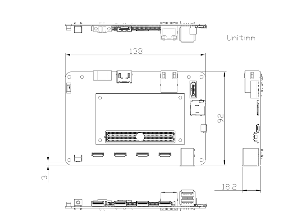
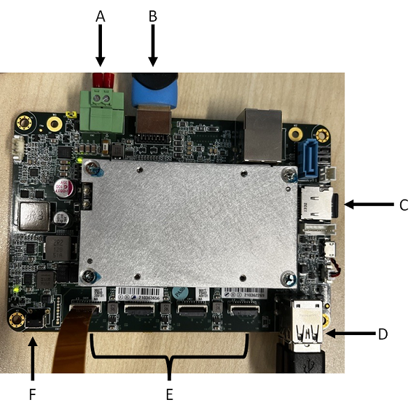
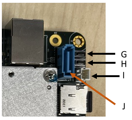
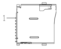
Dimensions and Physical Interface
 |
A | Power In Connector |
| B | HDMI Connector | |
| C | Micro SD Card Slot | |
| D | USB3/USB2 Connectors | |
| E | USB3 Connectors | |
| F | Power Switch | |
| G | Hardware Reset Switch | |
| H | Recovery Switch | |
| I | Mini 2 Pin to SATA Power | |
| J | SATA Connector |
See connector pinout descriptions below.
Installing a Camera
To boot up the Quartet:
1. Attach power adapter to the Power in connector. [A]
2. Attach HDMI cable to connect Quartet to your monitor. [B]
3. Insert Micro SD card into Quartet. [C]
4. Attach mouse and keyboard with USB connectors. [D]
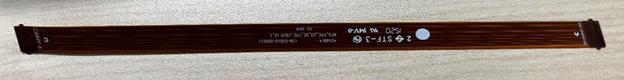
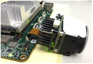
5. Connect the FPC cable to the camera and to the Quartet. There are four USB3 ports. [E]
Note: the FPC cable is labelled camera and accessories. Ensure the camera end is in the camera and the accessories end is in the Quartet.
6. Switch the power on. [F]
7. Login to the board with ID = nvidia and password = nvidia
We recommend changing the login ID and password from the default immediately after your initial login.
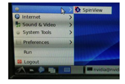
8. Open the SpinView application to test the camera.
How to Flash the SD Card and Bootloader Firmware for Quartet
Note: This section is not required for users who purchased their Quartet board directly from Teledyne FLIR.
If you purchased your Quartet from a third-party you need to flash your Micro SD card and flash bootloader firmware to eMMC to be able to boot up the board and use the Spinnaker SDK.
You need the following components:
- PC equipped with:
- Ubuntu 16.04, 18.04, or 20.04
- Python installed
- At least 30 GB of free space
- 16 GB (or larger) Micro SD card
- USB2 A-Male to Micro-B cable
- Micro SD card reader connected to the PC through a USB3 port
To flash the SD card:
1. On the PC download the Etcher flash tool from https://www.balena.io/etcher/
2. Download the image for Quartet from:
3. In a terminal extract the image file with the following command:
- 4 GB TX2 module: $ tar -xvf ACLinux_4.9_ACLNX49D.NV02.BOXER-8150AI-B1-FLIR.2.tar.gz
- 8 GB TX2 module: $ tar -xvf ACLinux_4.9_ACLNX49D.NV02.BOXER-8150AI-B1-FLIR.9.tar.gz
4. Launch the Etcher flash tool.
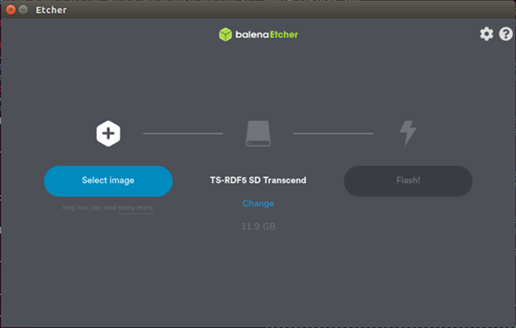
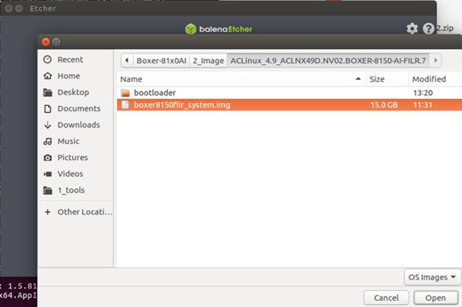
5. Click Select image and open the file extracted in previous step.
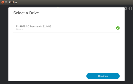
6. Insert the SD card into the card reader attached to the PC. Click Change and select the correct device. Click Continue.
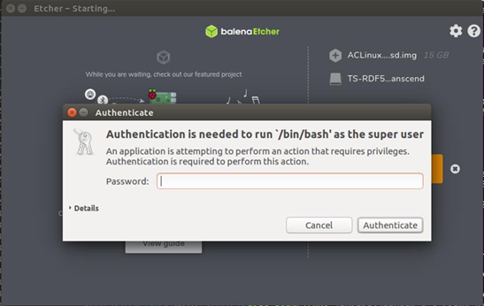
7. Click Flash! You may be prompted to enter an administrator password to proceed. Enter your password and click Authenticate.
A Flash Complete success message appears.
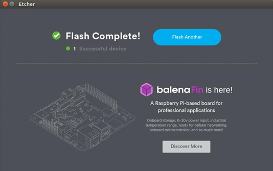
8. Remove the SD card from the reader and insert it into the Quartet.
To flash the bootloader firmware to eMMC:
1. Connect the PC to Quartet with the USB2 cable.
2. Enter recovery mode on the Quartet with the following steps:
- Power on
- Press and hold recovery button
- While holding recovery button, press and hold reset button
- Wait 2 seconds
- Release reset button
- Release recovery button
3. Extract the image file:
- 4 GB TX2 module: $ tar -xvf ACLinux_4.9_ACLNX49D.NV02.BOXER-8150AI-B1-FLIR.2.tar.gz
- 8 GB TX2 module: $ tar -xvf ACLinux_4.9_ACLNX49D.NV02.BOXER-8150AI-B1-FLIR.9.tar.gz
4. Navigate to the bootloader folder.
5. Run the flash command:
./flashall.sh
If successful, you will see a screen similar to:
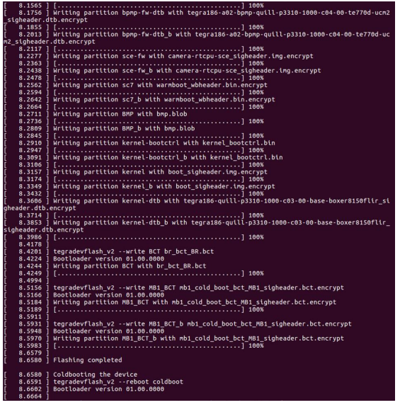
6. Disconnect and reconnect the power to boot the Quartet.
Setting Auto Power Jumpers
The Quartet is configured by default to use an ATX power supply. This can be changed to an AT power supply by switching the Auto Power jumpers from open to closed. The Auto Power jumpers are located next to the power in connector.
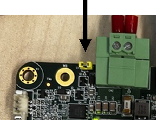
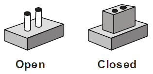
Setting Jumpers
A jumper is a simple electric switch which consists of two metal pins and a metal clip that slides over the pins to connect them. The metal clip is often protected by a plastic cover. To close the jumper, connect the pins with the clip. To open, remove the clip. A pair of needle-nose pliers may be helpful.
Connector Pinout Descriptions
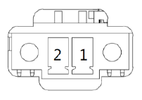
A—Power In Connector
 |
|
B—HDMI Connector
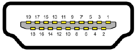
| Pin | Signal | Pin | Signal | |
| 1 | HDMI_DATA2_P | 11 | GND | |
| 2 | GND | 12 | HDMI_CLK_N | |
| 3 | HDMI_DATA2_N | 13 | NC | |
| 4 | HDMI_DATA1_P | 14 | NC | |
| 5 | GND | 15 | HDMI_SCL | |
| 6 | HDMI_DATA1_N | 16 | HDMI_SDA | |
| 7 | HDMI_DATA0_P | 17 | GND | |
| 8 | GND | 18 | HDMI_PWR | |
| 9 | HDMI_DATA0_N | 19 | HDMI_HDP | |
| 10 | HDMI_CLK_P |
C—Micro SD
 |
|
D—USB 3.0 and USB 2.0 Connector
 |
|
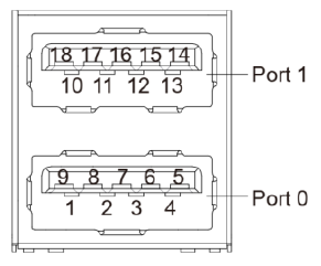
E—USB 3.0 Port Connector (TF-38)
| Pin | Signal | Pin | Signal | |
| 1 | +5 V | 10 | GND | |
| 2 | +5 V | 11 | USB3 TX N | |
| 3 | GND | 12 | GND | |
| 4 | GND | 13 | USB3 TX P | |
| 5 | D- | 14 | GND | |
| 6 | GND | 15 | USB3 RX N | |
| 7 | D+ | 16 | GND | |
| 8 | GND | 17 | USB3 RX P | |
| 9 | 18 | GND |
I—SATA Power Port
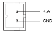 |
|
J—SATA Port
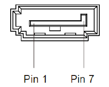 |
|
Additional Connectors
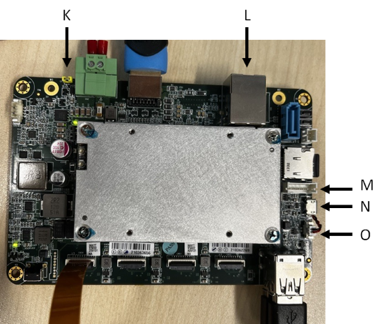
K—Auto Power Button
 |
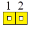 |
| Disable (Default) | Enable |
| Function | |
| 1-2 | Open ATX (Default) |
| 1-2 | Closed AT |
L—LAN RJ-45 Connector
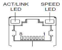 |
|
M—UART Debug Connector
| Pin | Signal |
| 1 | +3.3 V |
| 2 | UART CTS |
| 3 | UART TX |
| 4 | UART RTS |
| 5 | UART RX |
| 6 | GND |
N—USB 2.0 OTG Connector
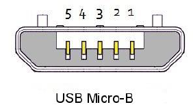 |
|
O—RTC Battery Connector
| Pin | Signal |
| 1 | +3 V |
| 2 | GND |